QO-100 - Es'Hail 2 Geostationary Satellite
This project started in January 2021 when I constructed a QO-100 (OSCAR 100) / Es'Hail 2 satellite station. The aim was to enable me to work through the geostationary satellite. I have listed below some of the key components, transmission and reception chains.
In 2025 I sold this setup and looked to change how I work QO-100. I will update this page when I decide how I am going. Below is the project as it was.
Receive Chain
The signal from the satellite's narrow band transponder is received on 10.489 GHz. This signal is mixed with the local oscillator (9.75 GHz) in the LNB, and the IF frequency is 739 MHz. The IF is forwarded through a pre-amp to boost the signal and then filtered to remove unwanted frequencies. The signal then goes to the SDR dongle where it is decoded and displayed. The Bias-T supplies power to the LNB while being transparent to RF.
Transmit Chain
A Yaesu FT-817 transmits on 432 MHz with an output of 1 to 3W. The transverter converts the signal from 432 MHz to 2400 MHz at with an output power of 250mW. The signal is then amplified to 6W 12W and radiated towards the satellite by a POTY patch antenna, mounted facing the dish.
Transmitter and Receiver build
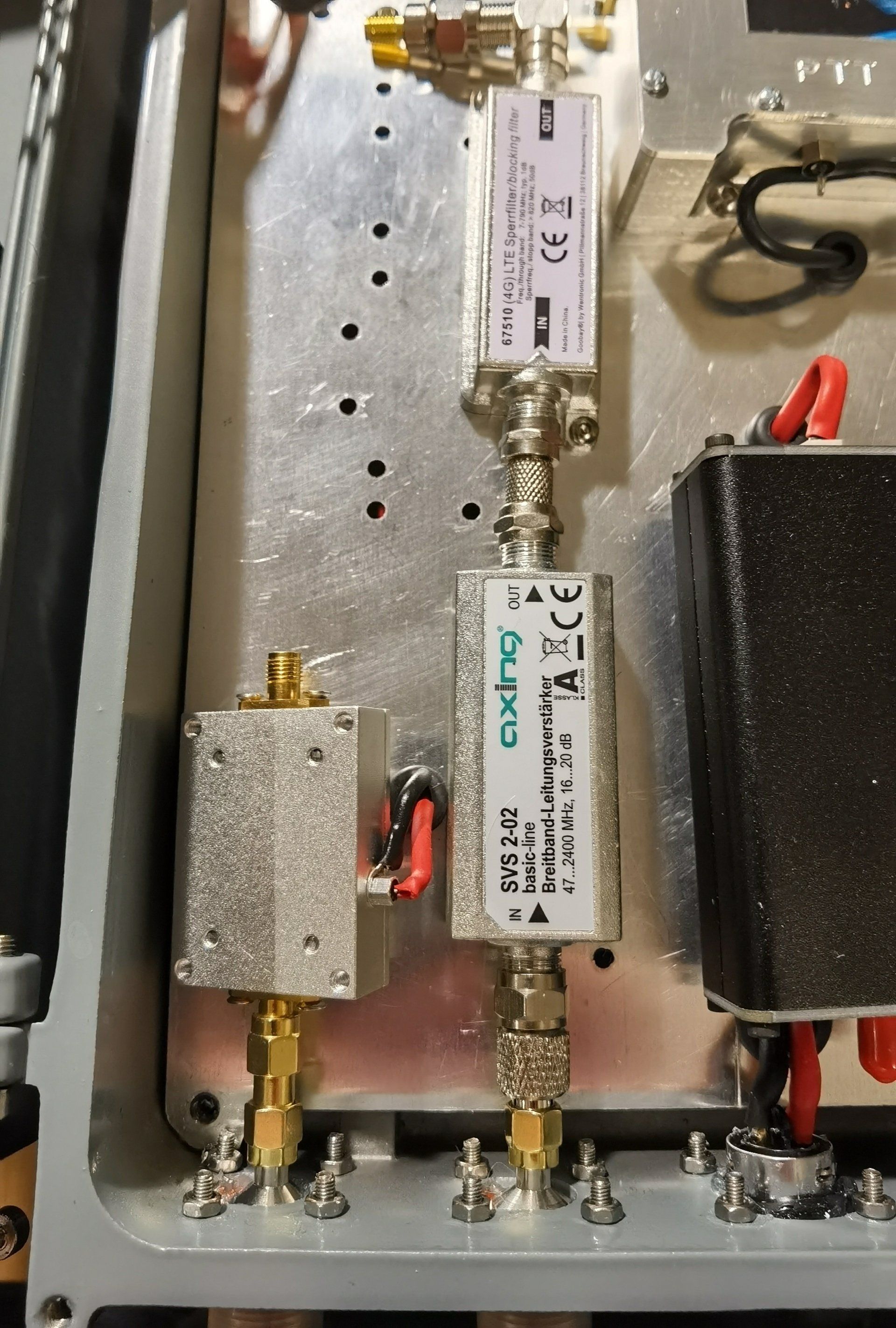
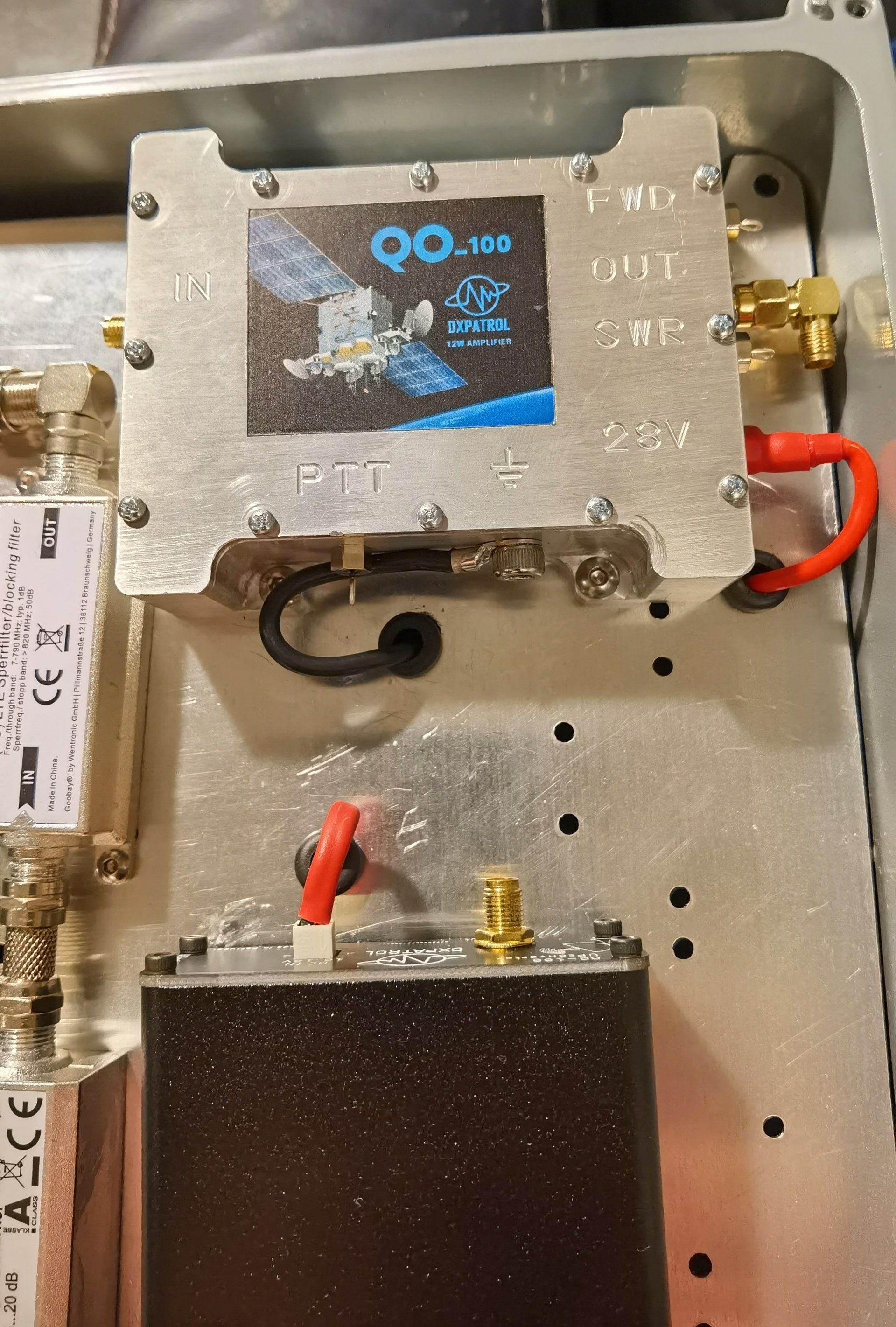
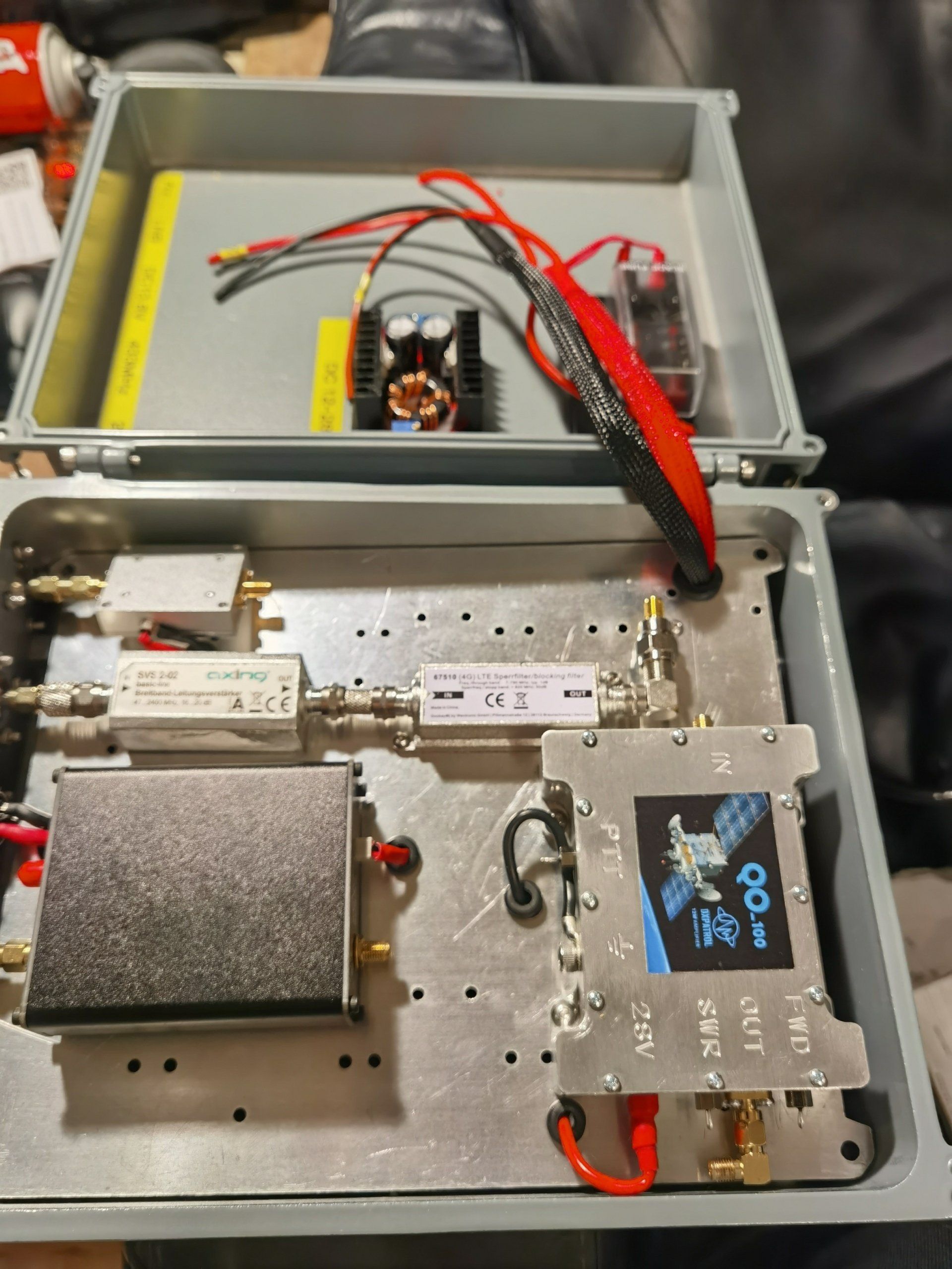
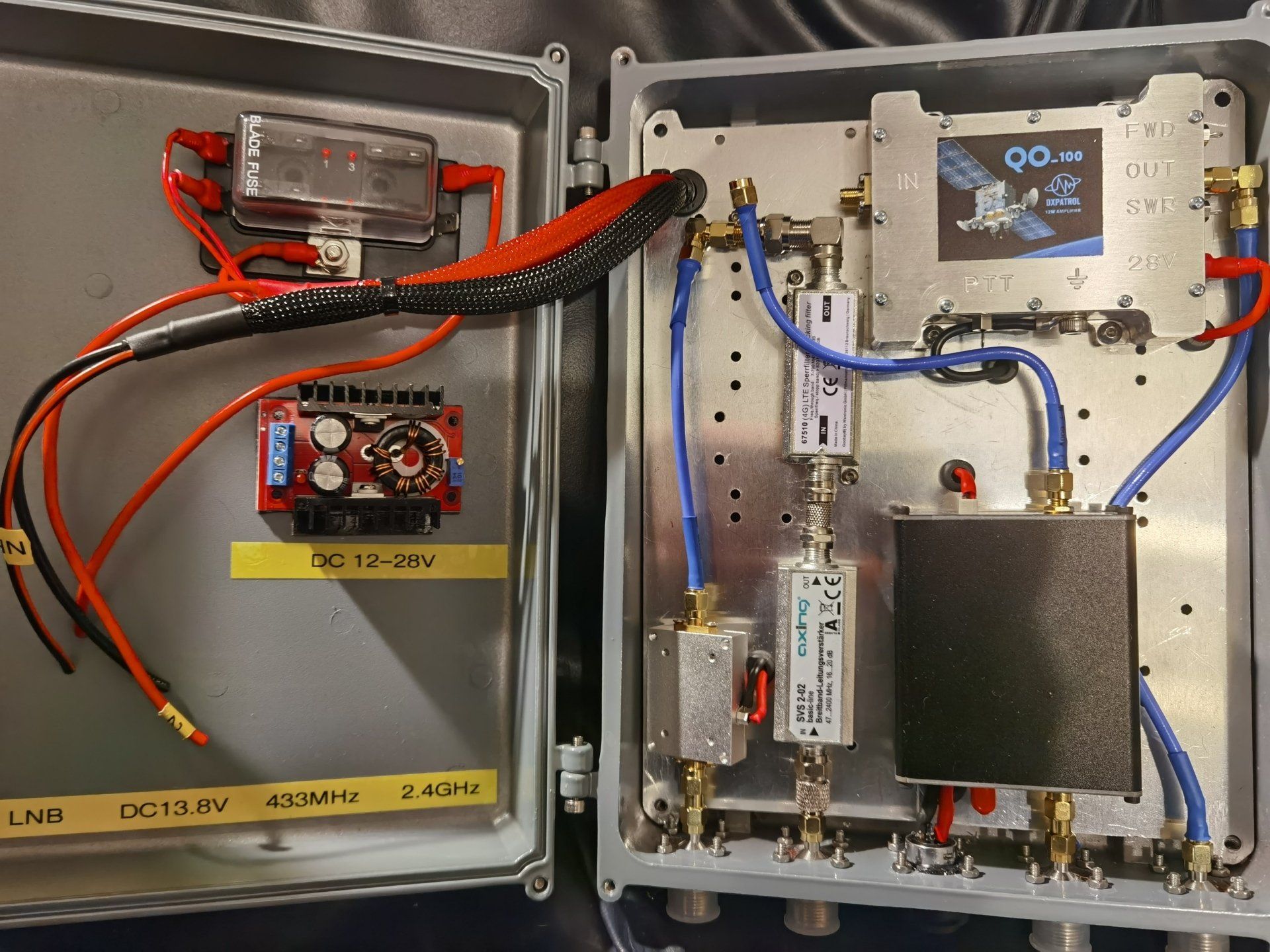
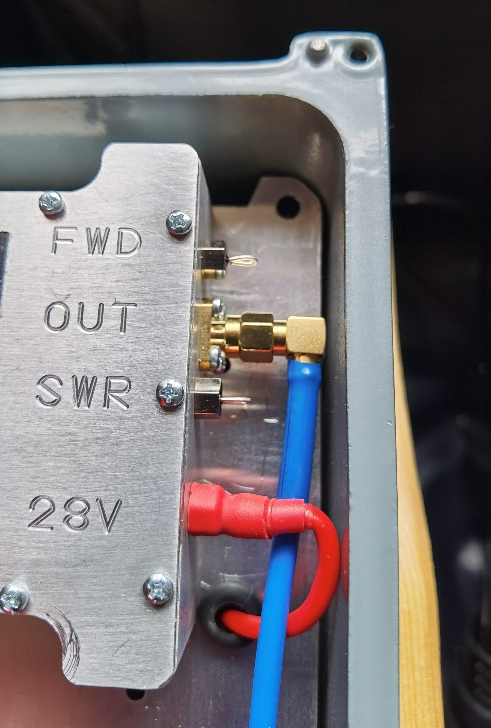
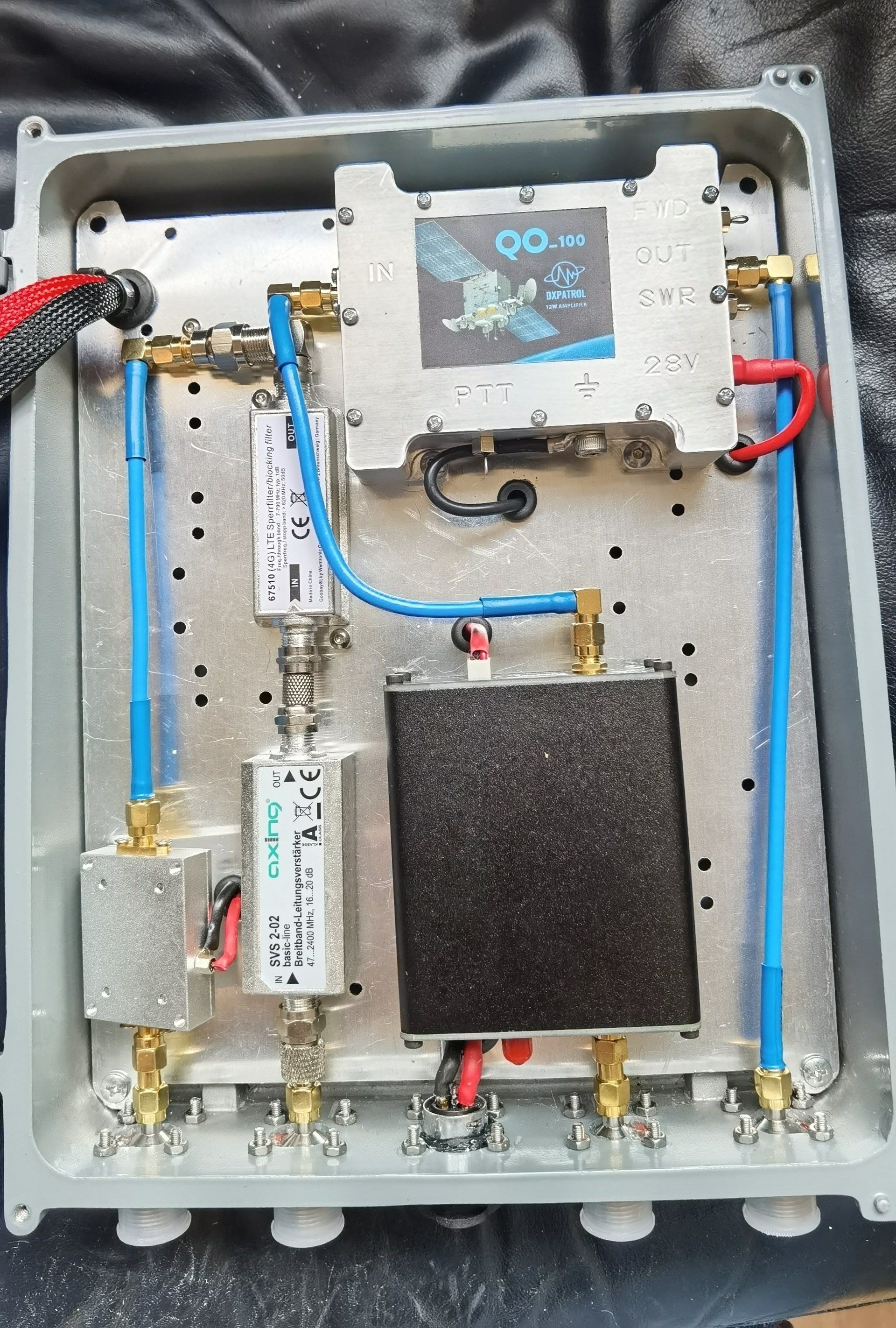
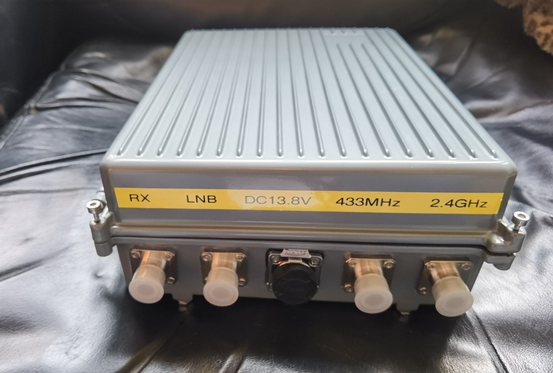
I decided to build a dedicated unit to house the main components of the up and down links. This way they could be housed next to the satellite dish and keep the coax cable run from the amplifier to the dish as short as possible. Here are a few pictures of the project build.
Up Converter - 433MHz to 2.4GHz
DX-Patrol QO-100 Up converter MK3
- Fully lockable into a internal TCXO 10 Mhz reference or a external GPSDO
- Extreme accuracy and precision transmission frequency
- Local Oscillator has 4 factory pre-programmed frequencies for 4 IF usages
- Spurious emissions = < 50dB
- 200mW output 23dBm
- Local Oscillators uses a Analog Devices AF4351 synthesizer
- locked into 10MHz TCXO Clipped Sine Wave Oscillator Frequencies Stability 500ppb
- power supply 10 to 15V
- Current consumption 300mA
- Dimensions: 77mm/67mm
- Connectors SMA
- RF input 1 to 3 W (6W Max)
Antenna
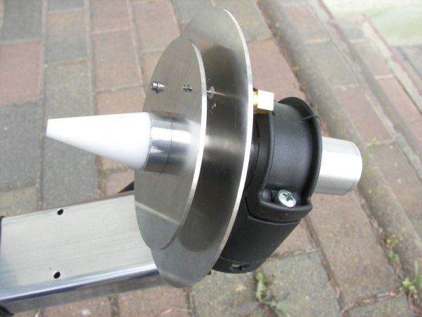
DualBand Feed 2.4 & 10 GHz DJ7GP V2 Antenna
- TX Frequency: 2.4 GHz Left Circular Polarization (LHCP)
Frequency RX: 10.5 Ghz linear polarization converts to 739Mhz via the LNB head to power with a Bias-T - Diameter of the antenna: 10,7cm
- Antenna impedance: 50 Ohms
- Power Max.: 50 Watts
- Setting the SWR: By screw on the antenna (original preset for QO-100 frequencies)
- RX Output LNB Opticum Single LSP-02G
- Antenna Connector 1: Female SMA for 2.4Ghz
- Antenna Connector 2: Female F via LNB Head for 10 Ghz
- Material: Aluminum, stainless steel screws
- Diameter of the rod: Ø 23 mm
- Outer diameter of the largest disk: 11cm
- Amateur Radio Design: DJ7GP
Transmitter Amplifier
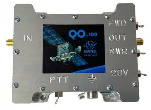
DX-Patrol QO-100 2.4GHz 12w Amp
- LDMos , rugged amplifier with aluminium box
- NXP MHT1008NT1 RF amplifier
- Designed for DXpatrol Upconverter as driver
- Input 70mW
- Output 12W* (5W if 12V supply)
- Voltage 28V ( 12V to 28V stepUP converter included)
- Bias current 600mA
- Max current 1,5A
- TX-Ground PTT
- Vox PTT
- SMA connectors
- Feed Trough capacitors
- SWR and POWER meter indication.
- SWR- Input 1:1.3 @ 50 Ohms
- Max VSWR output – 5:1
- Operating Temperature- 40ºC to 80ºC Max Temperature- 150ºC
- LDMOS- MHT1008NT1
- Driver- RF2126
- PWR meter DC 0V to 4V ( full power )
- SWR meter DC 1.5V@ SWR 1:1 /~/ 4V @ SWR Ꝏ
SDR Receiver
SDRplay RSP1A
- Model Number RSP1A
- Frequency Range 1kHz – 2GHz
- Antenna Connector SMA
- Antenna Impedance 50 Ohms
- Operating Temperature Range -10˚C to +60˚C
- Current Consumption (Typical) 185mA
- Case Size 95mm X 80mm X 30mm
- Case Weight 110 grams
- USB Connector USB Type B
- Maximum Input Power +0dBm Continuous +10dBm Short Duration
- ADC Sample Rates 2MSPS – 10.66MSPS
- ADC Number of Bits
14bit 2MSPS – 6.048MSPS
12bit 6.048MSPS – 8.064MSPS
10bit 8.064MSPS – 9.2
8bit >9.216MSPS
- Bias-T 4.7V 100mA Guaranteed
- Reference 0.5ppm 24MHz TCXO
- Frequency error trimmable to 0.01ppm in field
SDR Receiver Software
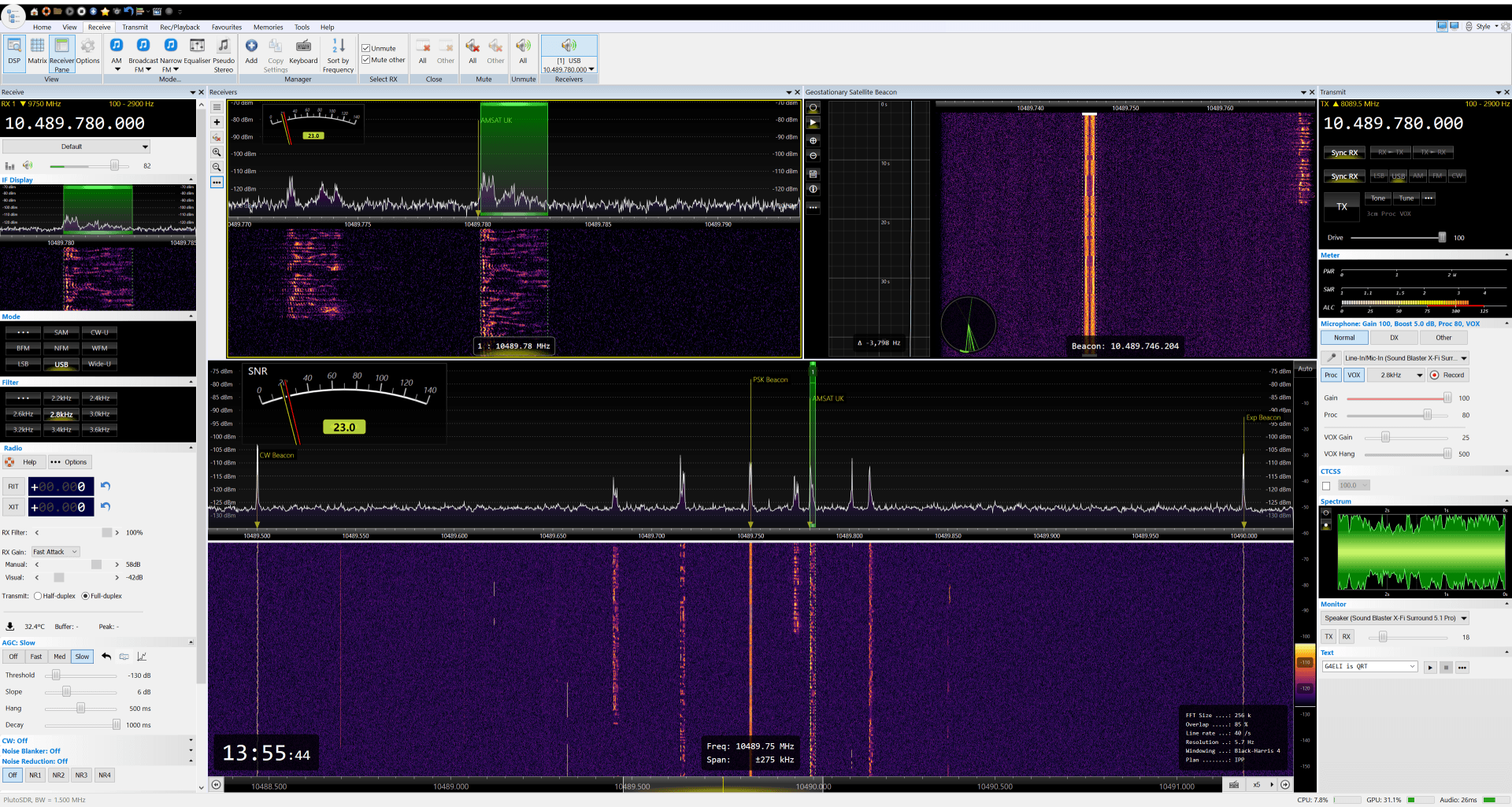
SDR Console
SDR-Radio.com is a Windows solution for Software Defined Radio (SDR) receivers and transceivers. Designed for the commercial, government, amateur radio and short-wave listener communities, this software provides a powerful interface for all SDR users.
System Coaxial Cables
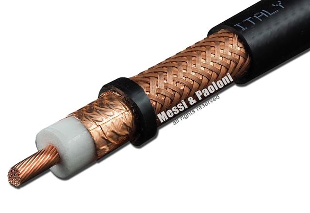
Messi & Paoloni 'Ultraflex 13'
- Impedence @200Mhz: 50 Ohm ± 3
- Minimum bending radius: up to 15 bends: 127mm (5.0 in) single bend (choke): 80mm (3.1 in)
- Temperature: -40°C to +60°C (-40°F to +140°F)
- Capacitance: 75 pF/m ± 2 (22.9 pF/ft ± 2)
- Velocity ratio: 86%
- Screening Efficiency (SA) 100-2000 MHz >105 dB
- Screening Class: A++
- Inner conductor resistance: 2 Ohm/Km (0.6 Ohm/1000ft)
- Outer conductor resistance: 11 Ohm/Km (3.0 Ohm/1000ft)
- Tension test (spark test): 8 kV
- Net weight (100m/100ft): 17,5 Kg (11.6 lb)
- Maximum peak power: 20.000 WATT
- Connectors: UHF (PL), N, 7/16


